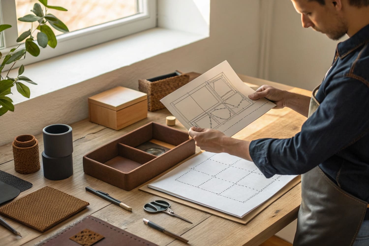
I see teams stall at the last mile of packaging. Files look pretty. Boxes fail on press. I fix that gap with clear dielines that print right.
Yes. I can provide a print-ready dieline and I can guide your team to adapt it. A dieline is the flat template that shows cut, crease, bleed, glue, and safety. If you follow it, your display prints, folds, and ships without surprises.
You came for a clear answer and a fast path. I will keep it simple, practical, and tied to cardboard displays for retail, trade shows, and club stores.
What is a dieline in packaging?
Many teams confuse artwork with structure. I did that on an early project. The result was color perfect, but the display collapsed in store. I learned the hard way that structure rules print.
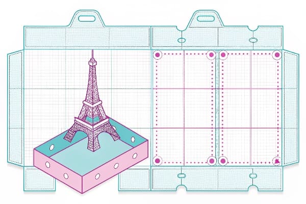
A dieline is a 2D technical template for a 3D package or display that marks cutting edges, folding creases, glue zones, bleeds, and safety areas so printers, CAD tables, and packers can build it correctly.

Why the dieline1 matters for cardboard displays2
A dieline is not art. It is a map. The map tells die makers where knives go and where scores go. It tells printers how far ink must extend past the cut (bleed) and how far text must sit inside (safety). It tells assembly where glue holds and where tabs lock. In my factory in Shenzhen, my team builds floor, pallet, and countertop displays every week. We start from board grade and payload, then we design the structure in CAD, then we export the dieline for design and prepress. This order saves time. It also avoids rework. My clients in hunting and outdoor gear want tight schedules. A correct dieline avoids failed transport tests and missed launches.
Common dieline layer legend
| Layer / Mark | Purpose | Typical Style |
|---|---|---|
| Cut line | Knife path | Solid magenta (overprint) |
| Crease/score | Fold lines | Dashed cyan |
| Bleed | Ink past trim | 3–5 mm outside cut |
| Safety | Keep text inside | 3–5 mm inside cut |
| Glue area | Adhesive zone | 20–25% tint spot |
| Reg marks | Press control | Black registration |
How to make dieline for packaging?
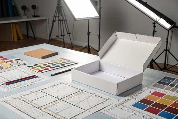
I keep the process short and strict. I start with load and retail rules. I choose board. I model the structure. I only bring in graphics after the dieline is stable.
You can make a dieline by defining size and load, choosing board grade, building a 3D CAD net, exporting a 2D template, adding bleed and safety, labeling layers, and running a test cut.

Step-by-step process I use in production
I begin with constraints. A big box retailer might cap height, base size, and shippable pallet footprint. I note product weight and center of gravity. I pick a corrugated grade that matches load and shelf life. I use CAD software3 to design the net: flaps, tabs, and locks. I simulate folds and stress. I export the dieline4 as vector paths. I add bleed outside all cuts and set a clear safety inside. I define spot colors for cut and crease. I add glue panels and tuck slots. I add barcodes and assembly numbers on separate layers. I print to a CAD cutter for a white sample. I load test and drop test. I correct tiny things now, not after print. When the structure passes, I hand the dieline to designers. They place art on a linked layer, not on the structure layers. We preflight in PDF/X. We run one printed prototype. We approve, then we go to mass production.
Toolchain and checks
| Stage | Tool | Checkpoint |
|---|---|---|
| CAD net | ArtiosCAD / Impact / Illustrator + plugins | Fold sim, tab fit |
| Dieline export | PDF (vectors), locked spot colors | Overprint on tech lines |
| Art placement | Illustrator / InDesign | Bleed and safety respected |
| Sample | CAD table / plotter | Fit, load, transport |
| Prepress | RIP with trapping | Ink coverage, barcode zone |
| Press | Litho/Direct print | Color, registration, crush |
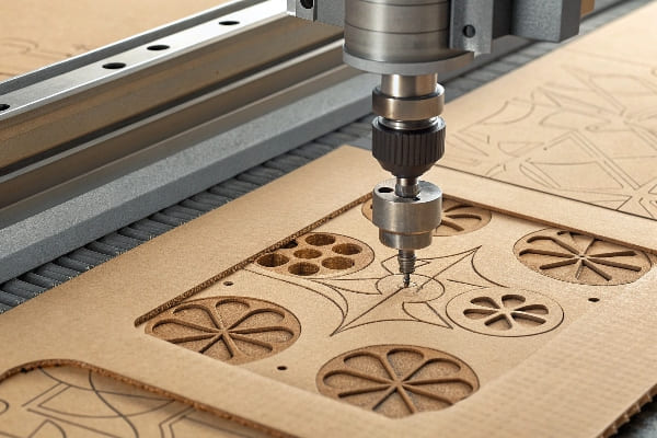
Why is it called a dieline?
Clients ask this a lot. The term sounds abstract. It is not. It comes from the tool that cuts the shape. That tool is the die.
It is called a dieline because it shows the path followed by a cutting die and the positions of scoring rules, so toolmakers and printers can manufacture the physical die and align print.
A quick history and how the name shapes practice
A die5 is a tool. In corrugated, it is often a flatbed board with steel rules for knives and scores. In high-speed work, it can be a rotary cylinder. The dieline6 is the drawing that defines where those rules sit. The name stuck because the drawing controls the die. In my factory, our toolmaker builds the die from the approved dieline, not from the artwork. If the dieline is wrong, the die is wrong. If the die is wrong, the press wastes sheets. This is why I lock the dieline layer and I forbid edits from anyone outside prepress. I tag versions with date and board grade. I add a small QR code that links to assembly video. This way, store staff fold it right the first time and returns drop.
Term, tool, and workflow
| Concept | What it is | Why it matters |
|---|---|---|
| Die | Knife and score tool | Determines cut accuracy |
| Dieline | Technical drawing | Guides die making and art |
| Rule height | Steel rule thickness | Affects crush and fold |
| Make-ready | Press setup | Saves time and sheets |
| Registration | Color alignment | Protects edges and text |
What are the standards for dieline?
Standards keep projects safe when timelines are tight. I sell B2B, so simple rules beat guesswork. I share the same checklist with every buyer.
Follow clear standards: correct board grade, minimum bleed and safety, locked spot-color tech lines, barcode quiet zones, pallet footprints, and export to press-ready PDF/X with outlined dieline layers.
Practical standards I enforce on every project
I keep board selection7 tied to load. Single-wall E or B flute serves light kits. Double-wall BC handles heavy floor units. My minimum bleed is 3 mm for litho-lam and 5 mm for direct print. My safety is at least 3 mm from any cut, 6 mm near perforations. I set cut lines as a spot color named "CUT", 100% tint, set to overprint. I set crease as "CREASE", dashed, also overprint. I shade glue panels at 20–25% tint. I protect barcode zones with a clean, unprinted quiet area. I define pallet footprints for club stores and add tie-down marks. I export PDF/X-48 with fonts embedded and images at 200–300 ppi effective. I preflight with a checklist. I run a white and a printed prototype. I log results from load and drop tests. I sign off with the buyer. We lock the file. We only reopen if change orders come.
My standard checklist
| Item | Rule | Pass/Fail Notes |
|---|---|---|
| Board grade | Matches load and shelf life | |
| Bleed | 3–5 mm | |
| Safety | ≥3 mm (≥6 mm near perf) | |
| Tech lines | Spot, overprint, labeled | |
| Glue zones | Marked, no ink in glue | |
| Barcodes | Clear quiet zone | |
| PDF/X | Fonts and images safe | |
| Prototypes | White + printed, tested |
Conclusion
A good dieline saves time, money, and brand trust. I build it first, test it early, and lock it before art. Your display will work in the real world.
Understanding dielines is crucial for effective packaging design, ensuring accuracy in production and avoiding costly mistakes. ↩
Exploring the process of making cardboard displays can provide insights into effective marketing strategies and design techniques. ↩
Explore this link to discover top CAD software that can enhance your packaging design process. ↩
Learn how to create an effective dieline, crucial for successful packaging production. ↩
Exploring the concept of a die can enhance your knowledge of manufacturing processes and improve production efficiency. ↩
Understanding dielines is crucial for ensuring accurate die production and preventing costly errors in printing. ↩
Understanding board selection can enhance your packaging's durability and effectiveness. ↩
Exploring PDF/X-4 can improve your print quality and ensure compatibility across different platforms. ↩