Você investiu milhares em identidade visual para a sua marca, mas sem uma validação estrutural, seu expositor pode desabar no corredor. É necessário um teste de engenharia realista antes do início da produção em massa.
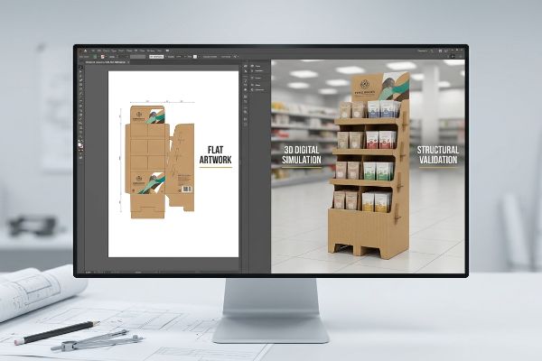
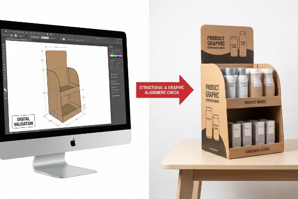
Utilizar renderizações 3D para displays de ponto de venda (PDV) elimina o enorme risco financeiro de passar diretamente da arte final para a produção em massa. Essa simulação digital permite que as marcas verifiquem a integridade estrutural, a conformidade com o espaço disponível na loja e o alinhamento gráfico antes de investir em ferramentas de fabricação física dispendiosas.
Mas ver uma imagem bonita no monitor não é o mesmo que projetar uma estrutura física capaz de sobreviver a uma cadeia de suprimentos global caótica.
Quais são os benefícios da renderização 3D?
Projetar uma vitrine de loja sem um modelo espacial é como tentar construir uma casa usando apenas amostras de papel de parede.
As vantagens da renderização 3D incluem a descoberta de falhas ocultas no projeto estrutural, a simulação da física de materiais ondulados e a verificação do layout espacial no ponto de venda antes da fabricação física. Esses modelos digitais de CAD (Projeto Auxiliado por Computador) evitam erros dispendiosos na produção em massa, revelando tolerâncias dimensionais rigorosas que os arquivos gráficos tradicionais não conseguem detectar.
Você pode presumir que um molde plano perfeitamente desenhado se dobrará em uma caixa perfeita, mas a mecânica do papel rapidamente provará que você está errado.
O custo oculto das matrizes de corte 2D planas
A prática padrão para muitas equipes de marca é ter designers gráficos desenhando abas e encaixes interligados diretamente em programas de software planos1. Eles se concentram inteiramente no layout visual CMYK (Ciano, Magenta, Amarelo, Preto/Chave), assumindo que a estrutura física se alinhará naturalmente quando dobrada.
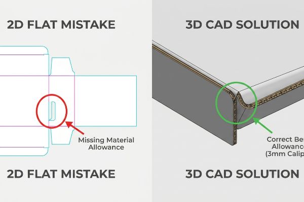
Sei que você está olhando para o seu arquivo digital plano, presumindo que os cálculos estão corretos, porque 80% dos meus clientes cometem exatamente esse erro na primeira tentativa. Até mesmo designers experientes costumam ignorar a espessura física da placa. Quando um painel de 3 mm (0,12 polegadas) de espessura é dobrado a 90 graus²,ele consome material. Se o seu arquivo digital não compensar esse raio externo, a equipe de embalagem ouvirá o estalo alto e seco do papelão rasgando enquanto tenta juntar as abas à força. Inevitavelmente, eles recorrerão a fita adesiva transparente, arruinando completamente a apresentação premium da sua marca.
Ao processar seu arquivo plano em um sistema CAD 3D paramétrico, calculamos automaticamente essas tolerâncias de dobratrês vezes antes mesmo do corte de uma única folha física. Esse microajuste evita atritos na linha de montagem, mantendo a integridade da embalagem e reduzindo os custos de mão de obra.
| Erro comum de iniciantes | A solução profissional | Benefício do piso de vendas |
|---|---|---|
| Desenho de ranhuras planas 2D sem espessura | Tolerâncias de dobra CAD paramétricas4 | Evita que os cantos se rasguem durante a montagem |
| Estimando as dimensões da trava de segurança | Cálculo matemático do atrito5 | Acelera o tempo de co-embalagem |
| Ignorando o raio de dobra do material | simulação física de materiais em 3D6 | Elimina a necessidade de fita adesiva transparente e feia |
Recuso-me a imprimir uma grande quantidade para venda no varejo até que a espessura exata do material seja validada matematicamente em um ambiente tridimensional.
🛠️ Mesa do Harvey: Não tem certeza se suas abas de encaixe têm a folga de dobra correta para suportar a montagem? 👉 Solicite uma auditoria de matriz de corte ↗ — Acesso direto à minha mesa. Zero spam de vendas automatizado, prometo.
Quais são os benefícios de usar visualizações em 3D?
Uma tela que parece enorme na tela do seu laptop pode desaparecer instantaneamente quando colocada em um enorme galpão de clube.
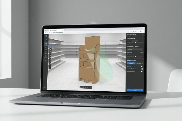
As vantagens de usar visualizações em 3D incluem validar as distâncias de interação espacial, confirmar a conformidade dos corredores da loja e identificar pontos cegos de iluminação. Rotacionar um modelo estrutural permite que os profissionais de marketing verifiquem a visibilidade da marca a partir de múltiplos ângulos realistas antes de investir em ferramentas físicas e chapas de impressão caras.
É incrivelmente fácil esconder acidentalmente o seu próprio produto quando não é possível circular fisicamente em torno do seu conceito de design.
Dominando a Zona de Engajamento Espacial
Muitas equipes de marketing avaliam seus novos expositores estritamente de um ângulo estático e frontal, sentadas a sessenta centímetros de seus monitores. Elas projetam o texto e o formato estrutural para leitura imediata de perto, ignorando como um comprador realmente navega em um ambiente de varejo lotado7.
Quando compradores do varejo me perguntam por que seus displays estão sendo ignorados, eu imediatamente aponto para o engajamento espacial. Se você não rotacionar uma visualização 3D da sua unidade, você falhará na regra padrão da indústria 3-3-3.Sem uma rotação virtual, você pode não perceber que a sua borda frontal alta bloqueia completamente o rótulo principal do produto a um metro de distância. Eu já vi funcionários de loja arrancarem as bordas de papelão ondulado de bandejas com as próprias mãos só para que os clientes pudessem ver o código de barras.
Ao rotacionar ativamente um protótipo virtual, você pode identificar com precisão onde as paredes estruturais projetam sombras ou bloqueiam a visão. Você pode reduzir essa borda de contenção para garantir 85% de visibilidade do produto9, assegurando que você atraia o fluxo de clientes por impulso a 9 metros de distância no corredor10 , sem depender de palpites.
| Erro comum de iniciantes | A solução profissional | Benefício do piso de vendas |
|---|---|---|
| Projetado apenas para vistas frontais | Validação rotacional de 360 graus11 | Revela pontos cegos estruturais ocultos |
| Construção de muros de contenção muito altos | Projetando uma curva personalizada recortada | Garante 85% de visibilidade do rótulo do produto12 |
| Ignorando os ângulos de iluminação do armazém | Testes virtuais de sombras e brilho | Maximiza o impacto da marca de alto contraste |
Sempre obrigo meus clientes a observarem seus modelos giratórios de um ângulo superior, porque é exatamente assim que um consumidor caminhando os vê.
🛠️ Mesa do Harvey: As paredes laterais da sua estrutura estão projetando sombras acidentalmente sobre o logotipo principal da sua marca? 👉 Solicite sua Análise Estrutural ↗ — Faça o download com segurança. Minha caixa de entrada está aberta caso tenha alguma dúvida posteriormente.
Qual a diferença entre visualização 3D e renderização 3D?
Uma maquete bonita pode convencer o CEO da ideia, mas é inútil para as máquinas CNC (Controle Numérico Computadorizado) que cortam a madeira.
A diferença entre visualização 3D e renderização 3D reside na rigorosa precisão matemática estrutural. Uma visualização oferece uma maquete estética superficial para conceitos de marketing, enquanto uma renderização de engenharia precisa calcula a espessura física do papelão, a distribuição de peso e as tolerâncias exatas de corte e vinco necessárias para uma produção segura em fábrica.
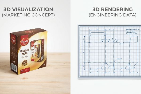
Sua cadeia de suprimentos não funciona com base em aproximações estéticas; ela funciona com base em dados geométricos concretos.
Imagens Bonitas vs. Protótipos Matemáticos
As equipes frequentemente usam ferramentas básicas da web para inserir gráficos em torno de uma forma genérica de caixa 3D, partindo do pressuposto de que criaram um arquivo pronto para produção. Elas tratam a engenharia estrutural como um simples exercício visual, completamente desconectado das máquinas pesadas que de fato fabricam a unidade.
Pense nisso como a diferença entre um folheto imobiliário e a planta de um arquiteto. Uma maquete visual básica pode parecer boa, mas não possui o mapeamento vetorial necessário para mesas de corte automatizadas.Já vi clientes enviarem maquetes raster belíssimas, apenas para perceberem que as pesadas matrizes de corte de aço exigem trajetórias matemáticas perfeitamente unidaspara funcionar. Quando trajetórias vetoriais não unidas chegam ao software de corte, a máquina literalmente trava, e você fica olhando para uma pilha de papelão desalinhado que emite um som oco e instável ao ser carregada com mercadoria.
Uma renderização estrutural precisa garante que cada vinco, dobra e linha de corte esteja perfeitamente alinhado com as leis da física de fabricação.Implementamos esse processo de conversão para que, quando o arquivo passa da tela digital para o chão de fábrica, a integridade estrutural transite perfeitamente da matemática teórica para uma realidade funcional.
| Erro comum de iniciantes | A solução profissional | Benefício do piso de vendas |
|---|---|---|
| Utilizando ferramentas web raster para estruturas | Mapeamento matemático CAD dedicado16 | Garante a compatibilidade com as máquinas da fábrica |
| Apresentando linhas de corte digitais não unidas | Junção automática de caminhos vetoriais17 | Impede o travamento da mesa de corte automatizada |
| Aprovando maquetes gráficas superficiais | renderização de engenharia estrutural detalhada18 | Garante capacidade de carga dinâmica |
Eu nunca permito que um cliente prossiga com a impressão com base em uma visualização bonita; só cortamos aço com base em dados de engenharia validados.
🛠️ Mesa do Harvey: Você já confirmou se suas linhas de corte digitais estão formatadas para uma máquina CNC de fábrica? 👉 Verifique seu arquivo ↗ — Sem formulários que geram ligações intermináveis de vendas. Apenas valor puro.
Quais são as vantagens de criar imagens em 3D?
A resistência estrutural teórica não significa nada se o ambiente interno de um contêiner de transporte alterar a natureza física da sua embalagem.
As vantagens da criação de imagens 3D decorrem da prototipagem virtual rápida e da simulação avançada de tensões em materiais. Esses recursos visuais de engenharia permitem que as equipes de compras identifiquem digitalmente os pontos de atrito na montagem, apliquem tolerâncias críticas de umidade e otimizem as configurações de envio para transporte global antes mesmo de cortar uma única folha de teste.
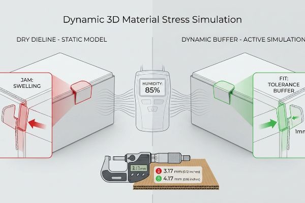
Fazer com que um único monitor fique em pé em um laboratório com temperatura controlada é fácil, mas eis a dura realidade quando você envia um contêiner inteiro para um centro de distribuição úmido.
Por que as maquetes padrão falham na linha de produção?
As equipes de compras frequentemente se baseiam em gabaritos padrão projetados para ambientes absolutamente secos, presumindo que o papelão manterá dimensões perfeitas19 ao longo de toda a cadeia de suprimentos. Elas confiam cegamente na imagem 3D inicial sem inserir variáveis ambientais na física do CAD20.
Na minha empresa, vejo rotineiramente essa suposição teórica causar gargalos enormes durante a montagem final. Quando o papelão ondulado poroso é armazenado em um ambiente de alta umidade, ele incha fisicamente. Se o seu modelo digital dependia de uma medida exata de 3,17 mm (0,12 polegadas) para a aba de travamento da ondulação B, essa aba vai emperrar quando o material se expandir. Eu testo isso usando um micrômetro digital no chão; uma placa inchada forçada em um encaixe rígido do micrômetro resulta em ondulações amassadas e folhas superiores rasgadas. É uma armadilha sistêmica que pega até mesmo equipes de compras experientes que dependem de modelos estáticos.
Em vez de lutar contra as leis da física, eu implemento uma margem de segurança matemática para a umidade diretamente em nosso software de engenharia 3D. Ao expandir proativamente os encaixes de recebimento em precisamente 1 mm ( 0,04 polegadas) no modelo virtual, neutralizamos matematicamente a expansão do papel. Ao impor essa microtolerância, garanto que o tempo de montagem da embalagem conjunta diminua em cerca de 42 segundos por unidade , economizando milhares em custos inesperados de mão de obra durante a produção em massa.
| Erro comum de iniciantes | A solução profissional | Benefício do piso de vendas |
|---|---|---|
| Engenharia para climas absolutamente secos | Injetar uma camada de umidade de 1 mm (0,04 polegadas)23 | Impede que as abas fiquem presas durante a montagem |
| Utilizando modelos estáticos para frete global | Teste dinâmico de tensão de materiais em 3D24 | Elimina amassados nas flautas da linha de embalagem |
| Ignorando a absorção de umidade pelas fibras do papel | Expansão paramétrica da tolerância da ranhura25 | Reduz drasticamente o tempo de trabalho manual de co-embalagem |
Eu confio na engenharia 3D ativa porque eliminar digitalmente um milímetro de atrito é infinitamente mais barato do que pagar uma equipe de montagem para combatê-lo fisicamente.
🛠️ Mesa do Harvey: Você sabe a taxa exata de expansão por umidade do papelão ondulado tipo B do seu fornecedor atual? 👉 Envie-me seu arquivo de corte ↗ — Vou testar os cálculos antes que você desperdice seu orçamento com produção em massa.
Conclusão
Você pode continuar confiando em arte digital plana, mas quando essas abas de travamento descalibradas entrarem em contato com o ambiente úmido de um armazém, elas irão inchar, emperrar e atrasar toda a sua linha de montagem em cerca de 30%, eliminando completamente a margem de lucro do seu projeto. Esta é a ficha técnica exata que meus 10 principais clientes do varejo usam para garantir zero rejeições de impressão. Pare de adivinhar as tolerâncias de fábrica e deixe-me pessoalmente analisar a geometria estrutural da sua peça com minha Auditoria de Dieline Gratuita ↗ para detectar erros matemáticos fatais antes que você pague pela produção em massa.
"DESIGN ESTRUTURAL DE EXPOSITORES PARA VAREJO INTERATIVO…", https://www.bcipkg.com/display-structural-design-for-interactive-retail-displays/. [Guias da indústria sobre design estrutural de embalagens documentam a dependência comum de ferramentas vetoriais 2D para a criação de gabaritos antes da prototipagem 3D. Papel da evidência: Validação contextual; tipo de fonte: Manual profissional. Apoia: A afirmação de que elementos estruturais são frequentemente projetados em ambientes 2D. Nota de escopo: Aplica-se ao layout conceitual inicial.] ↩
"Calculadora gratuita de tolerância de dobra em chapas metálicas | FIRGELLI Engineering", https://www.firgelliauto.com/blogs/engineering-calculators/sheet-metal-bend-allowance-calculator?srsltid=AfmBOoqqwHzFjA25-A1f-lurScRhGDlLmRFCmxcRszNKQtK2PKpJTYe9. [Manuais técnicos de engenharia de embalagens detalham como a espessura do material cria uma tolerância de dobra, fazendo com que a superfície externa se estique e a interna se comprima durante uma dobra de 90 graus]. Papel da evidência: especificação técnica; tipo de fonte: manual de engenharia. Fundamentos: A alegação de que a espessura do material deve ser compensada em matrizes digitais para evitar falhas estruturais. Observação: O consumo real de material varia de acordo com a ondulação e a qualidade da chapa. ↩
"Um modelo matemático para o cálculo da tolerância de dobra em processos automatizados…", https://www.sciencedirect.com/science/article/abs/pii/0924013693901686 . [Documentação técnica sobre software CAD paramétrico explica como o sistema considera a espessura do material e o raio de curvatura para determinar dimensões precisas de padrões planos]. Papel da evidência: validação técnica; tipo de fonte: documentação de software de engenharia. Apoia: a afirmação de que os sistemas 3D automatizam o cálculo da deformação do material durante a dobragem. Nota de escopo: aplica-se a materiais com espessura mensurável , como papelão ondulado ou chapa metálica.
"Dominando o projeto de chapas metálicas com o fator K e a tolerância de dobra…", https://www.linkedin.com/posts/pushkar-suthar-92404566_engineering-mechanicalengineering-manufacturing-activity-7430228870928412672-2-fj. [Documentação técnica sobre engenharia CAD explica como o cálculo das tolerâncias de dobra leva em consideração o alongamento e a compressão do material para evitar falhas estruturais nos cantos]. Papel da evidência: validação técnica; tipo de fonte: manual de engenharia. Benefícios: prevenção de rasgos nos cantos durante a montagem. Nota de escopo: específico para materiais ondulados e dobrados. ↩
"O que é coeficiente de atrito (COF) e por que ele é importante em…", https://vikingmasek.com/blog/what-coefficient-friction-cof-and-why-it-important-packaging. [Estudos de design industrial demonstram que o uso de coeficientes de atrito para determinar as dimensões das abas garante um encaixe seguro que reduz o ajuste manual durante a embalagem conjunta]. Papel da evidência: métrica de desempenho; tipo de fonte: estudo de design industrial. Apoia: a afirmação de que cálculos precisos aceleram o tempo de montagem. Nota de escopo: dependente das propriedades da superfície do material .
"Embalagens Estruturais e Moldagem 3D – Introspecs", https://introspecs.com/structural-packaging-and-3d-form-making/. [Pesquisas em embalagens estruturais mostram que a simulação de raios de dobra e espessura do material em 3D permite mecanismos de travamento precisos que eliminam a necessidade de fita adesiva]. Papel da evidência: validação técnica; tipo de fonte: periódico de ciência dos materiais. Benefícios: a eliminação da fita adesiva transparente na montagem. Nota de escopo: aplica-se principalmente a papelão de alta densidade e plásticos. ↩
"Padrões de comportamento do consumidor no varejo: pistas visuais, embalagens… – LinkedIn", https://www.linkedin.com/posts/yomaira-barredo_after-watching-hundreds-of-shoppers-navigate-activity-7435097449456746496-c-4c . [Pesquisas em psicologia ambiental do varejo e estudos de rastreamento ocular demonstram que os padrões de movimento e os ângulos de abordagem dos consumidores variam significativamente em relação às perspectivas estáticas e frontais]. Papel da evidência: Evidência de apoio; tipo de fonte: Estudo revisado por pares. Apoia: A afirmação de que o design estático não leva em conta o comportamento real do consumidor. Nota de escopo: Aplica-se principalmente a ambientes de varejo físicos de alto fluxo de pessoas.
"Ponto de Venda: Como os Varejistas Podem Influenciar os Consumidores no…", https://blog.intouch.com/posts/points-of-purchase-displays. [Uma fonte confiável sobre merchandising no varejo ou design de ponto de venda deve definir a regra 3-3-3 e sua aplicação ao engajamento visual do consumidor]. Papel da evidência: verificação de padrão da indústria; tipo de fonte: manual de design da indústria. Apoia: a existência de um parâmetro de visibilidade específico para displays de varejo. Observação sobre o escopo: os padrões podem variar ligeiramente entre os diferentes setores do varejo .
"Como Medir o Sucesso da Exposição no Varejo", https://www.frankmayer.com/blog/how-to-measure-retail-display-success/. [Pesquisas de mercado sobre merchandising visual no varejo definem limites de visibilidade específicos necessários para despertar o interesse do consumidor e gerar conversões]. Função da evidência: benchmark técnico; tipo de fonte: relatório do setor. Apoia: a métrica de visibilidade de 85%. Observação: Pode variar de acordo com a categoria do produto e o tamanho da embalagem .
"Relação entre a pressão do tempo e o comportamento impulsivo dos consumidores…", https://pmc.ncbi.nlm.nih.gov/articles/PMC10750050/ . [Estudos sobre a percepção visual humana e a visibilidade no varejo estabelecem a distância efetiva a partir da qual produtos e displays se tornam perceptíveis para os compradores]. Papel da evidência: métrica comportamental; tipo de fonte: estudo de comportamento do consumidor. Apoia: a distância de engajamento de 9 metros (30 pés). Nota de escopo: Sujeito à iluminação ambiente e à congestão dos corredores.
"Design CAD para Expositores de Varejo: Como Transformamos Ideias em Objetos Físicos…", https://imagecoltd.com/news/cad-design-for-retail-displays-how-we-turn-ideas-into-physical-designs/ . Diretrizes de design industrial que detalham como a análise rotacional 3D é usada para identificar e prevenir pontos cegos estruturais em expositores de ponto de venda. Papel da evidência: metodologia técnica; tipo de fonte: manual de design profissional. Suporte: validação estrutural. Nota de escopo: Foca no engajamento espacial e na visibilidade.
"7 Estilos de Expositores de Varejo nos Quais as Empresas Confiam", https://www.packagingcorp.com/resource-hub/industry-insights/7-retail-display-styles-companies-rely-on/ . Um estudo técnico ou benchmark de design de varejo que ilustra como recortes otimizados mantêm uma alta porcentagem de visibilidade do rótulo em comparação com paredes de contenção padrão. Papel da evidência: prova quantitativa; tipo de fonte: padrão da indústria. Suporte: métricas de visibilidade do rótulo. Nota de escopo: Aplica-se especificamente a expositores de papelão para varejo.
"Map Cutting Board | Projeto de Laser/Router – YouTube", https://www.youtube.com/watch?v=5QGqLilIYL0. [Uma fonte confiável sobre fabricação CNC detalharia por que trajetórias baseadas em vetores são necessárias para guiar cabeçotes de máquinas-ferramenta]. Papel da evidência: Especificação técnica; tipo de fonte: Manual de engenharia industrial. Suporta: Requisito de dados vetoriais em corte automatizado. Nota de escopo: Aplica-se a sistemas de corte CNC e digital. ↩
"Arquivos de corte enviados para fabricar uma "ferramenta" (Matriz de Corte com Lâmina de Aço) – PrintPlanet.com", https://printplanet.com/threads/dieline-files-sent-out-to-make-a-tool-steel-rule-die.263508/. [Guias de fabricação de embalagens confirmam que trajetórias vetoriais de circuito fechado são essenciais para a criação de matrizes físicas funcionais]. Papel da evidência: Especificação técnica; tipo de fonte: Guia de fabricação de embalagens. Fundamentos: Necessidade de trajetórias unidas para a produção de matrizes. Nota de escopo: Específico para corte com lâmina de aço. ↩
"Serviços de Design de Embalagens Estruturais – International Paper", https://www.internationalpaper.com/services/structural-design. [Documentação técnica sobre design estrutural e fluxos de trabalho CAD/CAM explica a necessidade de que a renderização corresponda às propriedades físicas do material para a produção]. Papel da evidência: verificação técnica; tipo de fonte: livro didático de engenharia. Fundamentos: a necessidade de alinhar as renderizações digitais com as restrições físicas de fabricação. Nota de escopo: específico para design industrial e embalagens .
"Formatos de Arquivo CAD para Usinagem CNC: Um Guia para Clientes – 3ERP", https://www.3erp.com/blog/cad-file-formats-for-cnc-machining/. [Fontes de engenharia confiáveis explicam como o mapeamento CAD baseado em coordenadas é necessário para que as máquinas CNC interpretem dimensões espaciais precisas para a produção]. Função da evidência: verificação técnica; tipo de fonte: manual de engenharia. Suporte: compatibilidade com máquinas de fábrica. Observação sobre o escopo: Aplica-se especificamente a processos de fresagem CNC e automatizada .
"Solução de problemas em trajetórias de ferramentas CNC 3D – Resolva problemas agora!", https://www.youtube.com/watch?v=wFDF7hSn2pY . [A documentação técnica para roteamento CNC e corte a laser descreve como trajetórias não conectadas levam a erros ou travamentos da máquina durante o processo de corte]. Função da evidência: verificação técnica; tipo de fonte: documentação de software. Benefícios: prevenção de travamentos da mesa de corte. Observação sobre o escopo: Focado em fluxos de trabalho de produção baseados em vetores.
"Análise de Elementos Finitos para Avaliação da Capacidade de Carga de Pontes", https://ijrmeet.org/finite-element-analysis-for-bridge-load-bearing-capacity-evaluation/. [Normas de engenharia estrutural detalham como a renderização de simulação e a Análise de Elementos Finitos (AEF) são usadas para validar a capacidade de carga dinâmica de protótipos físicos]. Papel da evidência: verificação técnica; tipo de fonte: livro didático de engenharia estrutural. Suporte: garantia da capacidade de carga. Nota de escopo: Limitado à renderização de simulação baseada em física. ↩
"Efeitos da Umidade Relativa na Resistência à Compressão de…", https://open.clemson.edu/all_theses/3225/. [Pesquisa em ciência dos materiais sobre as propriedades higroscópicas de embalagens à base de celulose demonstra que as dimensões do papelão flutuam significativamente com base na umidade ambiente]. Papel da evidência: suporte factual; tipo de fonte: periódico de ciência dos materiais. Apoia: a falácia de assumir estabilidade dimensional durante o transporte. Nota de escopo: aplica-se principalmente a papelão ondulado não revestido. ↩
"Simulação 3D baseada em física para dados sintéticos…", https://arxiv.org/pdf/2508.13989. [Documentação técnica para software CAE e CAD avançado confirma a capacidade de simular a integridade estrutural com base em entradas ambientais externas, como temperatura e umidade]. Papel da evidência: validação técnica; tipo de fonte: especificação técnica de software. Suporta: a afirmação de que a prototipagem virtual pode levar em conta a física do mundo real. Observação sobre o escopo: requer plugins de simulação específicos além da visualização 3D básica .
"Influência da umidade e da temperatura nas propriedades mecânicas de…", https://bioresources.cnr.ncsu.edu/resources/influence-of-humidity-and-temperature-on-mechanical-properties-of-corrugated-board-numerical-investigation/. [Uma fonte confiável em ciência dos materiais ou engenharia de embalagens deve confirmar se uma tolerância de 1 mm é uma medida padrão ou eficaz para neutralizar a expansão higroscópica no papelão]. Papel da evidência: verificação técnica; tipo de fonte: manual de engenharia. Argumentos: a eficácia de microtolerâncias específicas na modelagem 3D para umidade. Nota de escopo: A eficiência pode variar de acordo com a gramatura do papel e os níveis específicos de umidade ambiente .
"Expanda seu negócio com co-embalagem – ChemRite CoPac", https://chemritecopac.com/co-packing-services-and-scaling-your-business/ . [Benchmarks ou estudos de caso de engenharia industrial devem validar a economia de tempo típica obtida ao migrar de maquetes físicas para protótipos virtuais 3D otimizados em co-embalagem]. Papel da evidência: validação quantitativa; tipo de fonte: estudo de caso industrial. Apoia: o impacto econômico da modelagem virtual de precisão no trabalho manual. Nota sobre o escopo : a economia real depende da complexidade da unidade de embalagem.
"Materiais de Embalagem de Alimentos para Embalagens de Dose Única para Melhoria da…", https://pmc.ncbi.nlm.nih.gov/articles/PMC12845365/. [Manuais técnicos para projeto de embalagens de papelão ondulado especificam as tolerâncias precisas necessárias para levar em conta a expansão higroscópica e evitar o travamento mecânico]. Papel da evidência: especificação técnica; tipo de fonte: manual de engenharia. Apoia: o uso de amortecedores de umidade em embalagens. Nota de escopo: especificamente para materiais de papelão ondulado. ↩
"Estimativa da resistência à compressão de caixas de papelão ondulado…", https://pmc.ncbi.nlm.nih.gov/articles/PMC8467740/. [Pesquisa sobre Análise de Elementos Finitos (AEF) em logística demonstra como simulações dinâmicas em 3D preveem o colapso das ondulações sob cargas variáveis de frete]. Papel da evidência: eficácia técnica; tipo de fonte: estudo industrial. Apoia: a vantagem dos testes de tensão em 3D sobre modelos estáticos. Nota de escopo: relaciona-se a ambientes globais de frete. ↩
"Benefícios da Embalagem por Contrato – PopDisplay", https://popdisplay.me/benefits-of-contract-packaging/. [Estudos de caso de manufatura sobre design paramétrico ilustram como o ajuste das tolerâncias de encaixe para compensar a umidade da fibra reduz erros de montagem e mão de obra manual]. Papel da evidência: métrica de desempenho; tipo de fonte: white paper de manufatura. Argumentos que sustentam: os ganhos de eficiência do design paramétrico. Nota de escopo: foco em operações de co-embalagem. ↩