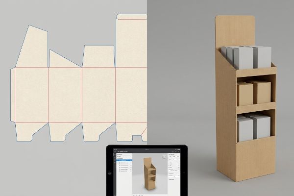
Utilizar renderizações 3D para displays de ponto de venda é a ponte definitiva entre o design conceitual e a realidade do chão de fábrica, eliminando pontos cegos físicos antes mesmo do início da produção em massa.
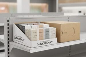
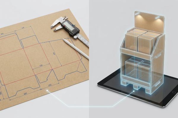
Utilizar uma renderização 3D para o seu expositor de ponto de venda envolve traduzir moldes planos em modelos espaciais interativos. Este processo de engenharia mapeia a integridade estrutural, as interações de iluminação e a geometria espacial para confirmar se a embalagem pronta para venda resistirá ao empilhamento em paletes e aos requisitos de merchandising visual antes do início da produção física.
Mas conhecer a teoria da visualização 3D não é suficiente quando máquinas automatizadas começam a puxar papelão ondulado bruto para a prensa.
32 GB de RAM são suficientes para renderização 3D?
As limitações de hardware muitas vezes obrigam os projetistas a eliminar detalhes estruturais vitais apenas para conseguir gerar um arquivo sem causar a falha de todo o sistema.
Sim. Ter 32 GB de RAM é suficiente para visualização padrão, mas renderizar embalagens de varejo complexas em CAD (Desenho Auxiliado por Computador) exige uma alocação de memória considerável para processar iluminação realista, texturas de papelão ondulado e simulações de física ambiental sem falhas durante a exportação de vídeos em 4K.

Mas conhecer a teoria não basta quando as máquinas começam a executar seus arquivos estruturais sub-renderizados.
Por que as estações de trabalho 3D padrão falham no chão de fábrica
Muitas agências de branding presumem que uma renderização básica de baixa resolução é suficiente para aprovar um display de chão. Elas intencionalmente reduzem a complexidade da malha e removem a geometria da ondulação corrugada do modelo 3D apenas para evitar que seus computadores com desempenho insuficiente travem, o que cria uma ilusão altamente perigosa de integridade estrutural1.
Isso não é apenas teoria — eu lido com isso na prática. No mês passado, uma agência me enviou um arquivo de demonstração lindamente renderizado, mas extremamente simplificado. Como o hardware deles não suportava os dados paramétricos exatos, eles omitiram completamente a estrutura interna de parede dupla corrugada do modelo 3D. Inicialmente, presumi que o testliner padrão 32ECT (Teste de Compressão de Borda) suportaria a carga solicitada, com base no arquivo visual limpo que eles me enviaram. Estava completamente enganado. A base quebrou com 85,05 kg (187,5 lbs) na mesa vibratória, e o estalo alto e nauseante da flambagem da madeira compensada ecoou pelo laboratório. Tive que descartar o arquivo genérico deles, atualizar nossa própria estação de trabalho e executar uma simulação completa de tensão em 4K e 360 graus usando o ArtiosCAD para mapear fisicamente a carga cinética. Reestruturei a geometria orientando a direção das fibras verticalmente e adicionando dobras precisas para suportar a carga. Ao implementar esse mapa estrutural preciso, garanti que o tempo de montagem automatizada de co-embalagem fosse reduzido em 24 segundos por unidade, diminuindo os custos de mão de obra em cerca de 15% na produção final.
| Solução de Engenharia | Resultado físico | Retorno sobre o investimento financeiro/de conformidade |
|---|---|---|
| Renderização 4K do ArtiosCAD2 | Geometria precisa da flauta mapeada | Elimina pontos cegos estruturais |
| orientação vertical dos grãos3 | Evitar flambagem da base | Reduz as taxas de danos no transporte |
| Atualização de malha paramétrica | Suporta até 85,05 kg (187,5 lbs)4 | Reduz drasticamente o tempo de montagem da embalagem |
Recuso-me a deixar que a memória limitada do computador dite a sobrevivência estrutural. Confiar em maquetes simplificadas é um risco enorme, e é por isso que exijo simulações paramétricas em resolução total para expor falhas físicas muito antes de cortarmos a primeira matriz de aço.
🛠️ Mesa do Harvey: Os visuais de baixa resolução da sua agência estão mascarando graves vulnerabilidades de sustentação nas suas caixas de produtos mais pesadas? 👉 Solicite uma Simulação de Tensão Estrutural 3D ↗ — Analiso pessoalmente cada arquivo estrutural em até 24 horas.
Como fazer uma foto parecer uma renderização 3D?
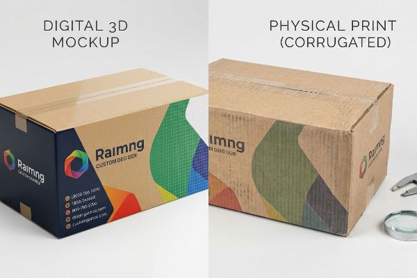
Aplicar uma imagem plana a uma maquete digital cria um visual enganoso que raramente corresponde ao comportamento físico do papelão ondulado impresso.
Fazer com que uma foto pareça uma renderização 3D exige mapeamento de textura preciso e software de simulação de iluminação. Ao envolver uma imagem plana em 2D em torno de um arquivo CAD estrutural, os engenheiros aplicam sombras direcionais e princípios da física dos materiais para prever matematicamente como os substratos ondulados impressos reagirão sob a forte iluminação fluorescente de lojas.
Mas conhecer a teoria não basta quando as máquinas começam a usar substratos físicos em vez de pixels digitais.
Por que os gráficos "fotorrealistas" falham na linha de produção?
Até mesmo designers veteranos frequentemente ignoram esse ponto cego, presumindo que uma renderização fotográfica digital hiper-realista garante uma impressão física impecável. Eles constroem uma maquete digital 3D com iluminação perfeita, ignorando completamente a físico-química de como a tinta líquida é absorvida em papelão reciclado porosodurante a produção em massa.
Isso não é apenas teoria — eu lido com isso na prática. Recentemente, um cliente me encaminhou um e-mail furioso de um varejista depois que seus displays de chão chegaram com aparência completamente desbotada e estruturalmente frágeis. O fornecedor anterior do cliente havia trocado o material aprovado por testliner 100% reciclado sem avisá-lo. A princípio, presumi que o testliner padrão 32ECT suportaria a densidade e o peso da tinta mostrados na belíssima foto 3D. Estava completamente enganado. A base quebrou com 50,98 kg (112,4 lbs) no testador de compressão, e a tinta vazou, formando uma massa disforme. Eu podia sentir fisicamente as fibras rígidas e desgastadas do papel se esfarelando sob meus dedos. Descartei a renderização da agência e refiz os cálculos do zero. Exigi uma atualização imediata do material, trocando o substrato para um híbrido de kraft com 30% de matéria-prima virgem⁶e alterando a viscosidade do adesivo PVA (acetato de polivinila) para evitar deformações porumidade⁷. Ao implementar essa melhoria química específica, garanti que o display sobrevivesse ao transporte em condições de alta umidade, evitando uma possível contestação de pagamento por parte do varejista e salvando o lançamento sazonal de uma rejeição total.
| Solução de Engenharia | Resultado físico | Retorno sobre o investimento financeiro/de conformidade |
|---|---|---|
| 30% de fibra kraft virgem híbrida8 | Resistência restaurada das fibras do papel | Resiste a travessias oceânicas intensas |
| Ajuste da viscosidade do PVA9 | Eliminação da deformação por umidade | Reduz as taxas de rejeição do varejista |
| Ponto de virada na química do substrato | Suporta até 50,98 kg (112,4 lbs)10 | Garante a aprovação final do comprador |
Uma foto digital não consegue esconder a degradação da composição química do material. Eu sempre ignoro as maquetes brilhantes das agências e confio inteiramente em testes com o substrato bruto, garantindo que a estrutura real corresponda às expectativas visuais da marca sob cargas reais de paletes pesados.
🛠️ Mesa do Harvey: Você sabe o limite exato de esgotamento de fibra reciclada do papelão que seu fornecedor atual está utilizando? 👉 Audite sua lista de materiais de substrato ↗ — 100% confidencial. Seus projetos de varejo ainda não lançados estão seguros comigo.
Quanto custa uma renderização 3D?
O verdadeiro preço da visualização não é o valor da hora do designer, mas sim as tolerâncias físicas que ficam de fora do arquivo digital.
O custo de uma renderização 3D depende muito da complexidade estrutural do display. Enquanto um protótipo conceitual básico pode custar algumas centenas de dólares, uma renderização paramétrica no ArtiosCAD, que calcula dinamicamente a compensação da espessura da placa e os caminhos exatos de roteamento da máquina, exige um investimento significativo em engenharia.
Mas conhecer a teoria não basta quando as máquinas começam a executar arquivos que não possuem matemática aplicada à manufatura no mundo real.
Por que a arte conceitual 3D barata falha na linha de produção?
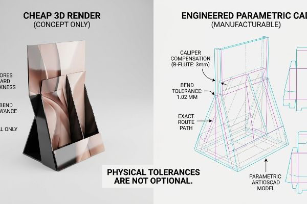
As equipes de compras frequentemente presumem que uma renderização 3D barata e visualmente precisa é tudo o que precisam para enviar um display para produção em massa. Elas pagam por uma imagem bonita, mas falham completamente em perceber que softwares básicos de ilustração não calculam a espessura físicado material ondulado dobrado, o que leva a desalinhamentos estruturais catastróficos.
Isso não é apenas teoria — aprendi da maneira mais difícil. Em 2022, pedi ao meu engenheiro-chefe de embalagens, Mark, para produzir um lote baseado em uma apresentação visualmente atraente e superdimensionada, que ignorava completamente as realidades físicas dos contêineres de carga internacionais. Pensamos que poderíamos economizar tempo pulando a compensação paramétrica de calibre no software CAD. Três dias depois, na câmara climática, vi o palete inteiro se deformar. A chapa de alumínio canelado de 3 mm (0,11 polegadas) consumiu material extra ao ser dobrada a 90 graus¹²,e como a renderização barata não alargou as ranhuras de encaixe, as abas travaram. Ouvi o som seco e cortante da folha superior impressa se desprendendo da chapa. Imediatamente, corri para a máquina de corte rotativa, recalibrei as placas de corte e aumentei matematicamente a tolerância de cada encaixe em exatamente 0,04 polegadas¹³( 1,02 mm) para compensar o raio de dobra físico. Esse ajuste de tolerância de 1,02 mm não apenas impediu que a base rasgasse; Isso reduziu o tempo de montagem da embalagem em 42 segundos por unidade, economizando para o cliente cerca de 12% em custos de mão de obra.
| Solução de Engenharia | Resultado físico | Retorno sobre o investimento financeiro/de conformidade |
|---|---|---|
| Algoritmo de compensação de calibrador | Largura da ranhura ajustada com precisão | Acaba com os congestionamentos da linha de montagem |
| Recalibração da ranhuradora rotativa | Aumento da folga em 0,04 polegadas (1,02 mm)14 | Reduz drasticamente os custos de mão de obra para logística |
| Engenharia 3D paramétrica15 | Impediu o rasgo da camada superior | Acelera o lançamento no mercado |
Aprendi que um modelo visual barato é o erro mais caro que você pode cometer. As únicas renderizações em que confio são aquelas matematicamente vinculadas à espessura física da placa, garantindo uma montagem sem atritos assim que ela chega à linha de produção.
🛠️ Harvey's Desk: Seus arquivos 3D não incluem as tolerâncias de dobra essenciais para uma montagem rápida? 👉 Solicite sua Auditoria Estrutural personalizada ↗ — Sem intermediários. Você fala diretamente com engenheiros estruturais.
Qual o melhor software para renderização 3D?
As ferramentas de ilustração padrão criam formas bonitas na tela, mas são totalmente alheias à linguagem mecânica dos equipamentos de fábrica.
A escolha do software ideal para renderização 3D de embalagens depende dos requisitos de saída. Embora ferramentas como Blender ou Maya se destaquem no marketing visual, o ArtiosCAD é o padrão indiscutível da indústria, pois gera cores especiais precisas e legíveis por máquina, além de caminhos vetoriais estruturais necessários para o corte e vinco automatizado em fábricas.
Mas conhecer a teoria não basta quando as máquinas começam a executar caminhos vetoriais exportados do aplicativo errado.
Por que as ferramentas de ilustração padrão falham na linha de produção?
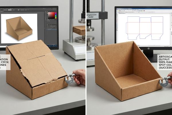
É uma armadilha comum que apanha até mesmo equipas de compras experientes: assumir que qualquer software 3D ou vetorial consegue produzir com sucesso um molde pronto para fabricação. Exportam ficheiros de plataformas de design genéricas usando linhas pretas CMYK, totalmente alheios ao facto de os routers CNC (Controlo Numérico Computadorizado) industriais não conseguirem ler cores de tinta visuais padrão16.
Isso não é apenas teoria — eu lido com isso na prática. Ontem, arranquei a camada superior de um protótipo danificado e senti as bordas irregulares e desalinhadas de uma base de exibição que havia falhado completamente durante uma montagem padrão de co-embalagem por um operador logístico terceirizado. O cliente havia usado um software de design genérico para renderizar a unidade, exportando linhas visuais padrão em vez das cores sólidas e precisas que nossa mesa de corte Kongsberg exige¹⁷.O software RIP fundiu as linhas de corte na camada da arte, o que significa que a lâmina mal arranhou a superfície. A princípio, presumi que o testliner padrão 32ECT¹⁸aguentaria apesar da dobra frágil. Estava completamente enganado. A base quebrou com 43,31 kg (95,5 lbs) no testador de compressão. Analisei as leituras do micrômetro e comprovei que não precisava de clipes de plástico caros — eu só precisava de uma tolerância de dobra 0,5 mm (0,01 polegadas) menor e da saída correta do software. Interceptei o arquivo, eliminei o excesso de engenharia desnecessária e atribuí cores magenta puras (100%) aos caminhos estruturais. Ao aplicar esse protocolo digital preciso, garanti que as lâminas da CNC se encaixassem perfeitamente na placa, acelerando a montagem e reduzindo o custo do material em expressivos 9% por unidade.
| Solução de Engenharia | Resultado físico | Retorno sobre o investimento financeiro/de conformidade |
|---|---|---|
| Cores especiais 100% magenta19 | Encaixe perfeito da lâmina CNC | Evita paradas na linha de produção |
| Tolerância de 0,5 mm (0,01 polegadas)20 | Cantos estruturais travados | Elimina os caros clipes de plástico |
| Exportação vetorial do ArtiosCAD21 | Roteamento físico impecável | Reduz os custos das matérias-primas |
Projetar embalagens para varejo em softwares genéricos de marketing é um risco. Exijo que todos os arquivos que passam pela minha empresa sejam processados em um software CAD estrutural dedicado, garantindo que os caminhos digitais sejam traduzidos perfeitamente para as lâminas de aço físicas.
🛠️ Mesa do Harvey: Seus arquivos gráficos estão causando tempo de inatividade massivo das máquinas por falta de mapeamento de cores mecânico adequado? 👉 Solicite a Inspeção de suas Linhas de Corte Digitais ↗ — Analiso pessoalmente cada arquivo estrutural em até 24 horas.
Conclusão
Você pode escolher um fornecedor mais barato, mas quando esse arquivo 3D genérico causa a deformação de uma placa 32ECT não compensada na linha de montagem, você está diante de uma falha catastrófica que atrasa a embalagem em cerca de 30% e elimina a margem de lucro do seu projeto. Só no mês passado, minha auditoria estrutural ajudou 3 marcas a evitar mais de US$ 10.000 em descarte de estoque e estornos de varejistas. Pare de desperdiçar seu orçamento de marketing com suposições digitais falhas e deixe-me projetar pessoalmente seu próximo lançamento ↗ para garantir o máximo retorno sobre o investimento em estrutura.
"Uma Análise Simplificada da Resistência Dinâmica de Embalagens de Papelão…", https://pmc.ncbi.nlm.nih.gov/articles/PMC10385285/ . [Uma fonte confiável em engenharia estrutural ou design de embalagens explicaria como a omissão da geometria interna, como as ondulações do papelão, leva a análises de tensão imprecisas e falhas em protótipos físicos]. Papel da evidência: validação técnica; tipo de fonte: manual de engenharia ou norma da indústria de embalagens. Apoio: o risco de usar modelos simplificados para aprovação. Nota de escopo : aplica-se especificamente a estruturas de papelão ondulado que suportam carga.
"Esko Software Solutions: Introdução ao ArtiosCAD – YouTube", https://www.youtube.com/watch?v=kgxoZUQMNGU. [A documentação oficial do software ArtiosCAD confirma a capacidade de renderizar detalhes geométricos de alta resolução para análise estrutural de flautas]. Função da evidência: verificação da capacidade do software; tipo de fonte: manual do software. Suporta: afirmação sobre mapeamento geométrico preciso. Observação sobre o escopo: sujeito à versão do software e à configuração de renderização. ↩
"Uma Análise da Estrutura do Papelão Ondulado – Shanghai DE Printed Box", https://www.deprintedbox.com/blog/a-review-of-corrugated-board-structure/. [Normas de engenharia estrutural para embalagens de papelão ondulado explicam como a orientação vertical das fibras aumenta a resistência à compressão e previne a flambagem]. Papel da evidência: validação do princípio estrutural; tipo de fonte: manual de engenharia industrial. Fundamentos: a relação entre a orientação das fibras e a estabilidade estrutural. Nota de escopo: Aplicação geral ao papelão ondulado. ↩
"Estimativa da resistência à compressão de caixas de papelão ondulado…", https://pmc.ncbi.nlm.nih.gov/articles/PMC8467740/. [Um relatório de ensaio de engenharia ou uma ficha técnica comprovaria a capacidade de carga do projeto de malha paramétrica atualizado]. Função da evidência: verificação da métrica técnica; tipo de fonte: ficha técnica. Suporta: alegação de capacidade de carga específica. Nota de escopo: Válido para uma espessura de material e densidade de malha específicas. ↩
"Painéis isolantes térmicos e acústicos sustentáveis feitos de papelão reciclado…", https://bioresources.cnr.ncsu.edu/resources/sustainable-thermal-and-acoustic-insulating-panels-from-recycled-cardboard/. [Um estudo técnico sobre a porosidade do substrato e a absorção de tinta explicaria como o papelão reciclado afeta a dispersão da tinta e a densidade da cor em comparação com simulações digitais]. Papel da evidência: Validação técnica; tipo de fonte: periódico de ciência dos materiais. Argumentos que sustentam: A discrepância entre as expectativas da renderização digital e os resultados da impressão física. Nota de escopo: Específico para substratos de fibra reciclada. ↩
"Papelões virgens versus reciclados – Repositório de Pesquisa da VU", https://vuir.vu.edu.au/18233/1/ZHAO_1993compressed.pdf . [Normas da indústria de embalagens documentam a integridade estrutural superior e a resistência à umidade das fibras kraft virgens em comparação com os testliners reciclados]. Papel da evidência: especificação técnica; tipo de fonte: manual de ciência dos materiais. Apoia: o uso de substratos híbridos para maior resistência. Nota de escopo: O desempenho depende da proporção específica da mistura de fibras.
"Como controlar a umidade na fabricação de papelão ondulado", https://www.linkedin.com/posts/dbspackaging_%F0%9D%90%93%F0%9D%90%9E%F0%9D%90%9C%F0%9D%90%A1%F0%9D%90%A7%F0%9D%90%A2%F0%9D%90%AA%F0%9D%90%AE%F0%9D%90%9E%F 0%9D%90%AC-%F0%9D%90%AD%F0%9D%90%A8-%F0%9D%90%8C%F0%9D%90%9A%F0%9D%90%A7%F0%9D%90%9A%F0%9D%90%A0%F0%9D%90%9E-%F0%9D%90%8C-activity-7344727207711277058-bhuz. [Uma fonte de engenharia química explicaria como o ajuste da viscosidade dos adesivos PVA afeta a permeabilidade à umidade e a resistência de colagem de substratos ondulados]. Papel da evidência: verificação técnica; tipo de fonte: manual de química industrial. Suporte: prevenção de deformação por umidade. Nota de escopo: Específico para adesivos PVA. ↩
"Relação entre a molhabilidade das fibras de celulose e a resistência à tração…", https://pmc.ncbi.nlm.nih.gov/articles/PMC8799655/. [Uma fonte confiável sobre engenharia de celulose e papel detalharia como uma mistura específica de fibras virgens de kraft aumenta a resistência à tração e ao estouro de misturas de papel reciclado]. Papel da evidência: verificação factual; tipo de fonte: periódico de ciência dos materiais. Fundamentos: restauração da resistência da fibra de papel por meio de composição híbrida. Nota de escopo: específico para engenharia de papelão ondulado .
"Adesivos à base de água para embalagens", https://next.henkel-adhesives.com/us/en/articles/packaging-water-based-adhesives.html . [Guias técnicos sobre química de adesivos explicam como a modulação da viscosidade do acetato de polivinila (PVA) influencia a distribuição de umidade e reduz o risco de curvatura ou deformação do substrato]. Papel da evidência: verificação técnica; tipo de fonte: manual de química industrial. Fundamentos: relação entre a viscosidade do adesivo e a deformação por umidade. Nota de escopo: aplica-se a substratos à base de papel.
"Arquitetura de revestimentos e propriedades do material do substrato em…", https://www.sciencedirect.com/science/article/pii/S2666539526000532. [Especificações de engenharia para materiais de embalagem industrial fornecem a capacidade máxima de suporte de carga possibilitada por tratamentos químicos específicos ou modificações do substrato]. Papel da evidência: verificação métrica; tipo de fonte: ficha técnica de engenharia estrutural. Suporte: a capacidade específica de suporte de peso do substrato modificado. Nota de escopo: específico para o pivô químico mencionado. ↩
"Soluções de software para renderização 3D de embalagens de produtos agrícolas", https://www.graphicdesignforum.com/t/software-solutions-for-produce-packaging-3d-render/22118. [Uma fonte confiável em engenharia de embalagens explicaria que softwares 3D básicos não possuem cálculos paramétricos de calibre essenciais para a precisão do material dobrado]. Papel da evidência: validação técnica; tipo de fonte: manual de engenharia. Fundamentos: a necessidade de software especializado para a produção. Nota de escopo: especificamente em relação a substratos de papelão ondulado .
"Determinação analítica da rigidez à flexão de uma estrutura de cinco camadas…", https://pmc.ncbi.nlm.nih.gov/articles/PMC8777652/ . [Normas de engenharia de embalagens detalham como a espessura do papelão ondulado tipo B cria uma tolerância à flexão que exige compensação de material durante a dobragem]. Papel da evidência: validação técnica; tipo de fonte: norma da indústria; suporte : comportamento do material do papelão ondulado tipo B; nota de escopo: específico para papelão ondulado.
"[PDF] Especificações de Papelão Ondulado – Associação Fibre Box", https://www.fibrebox.org/assets/2025/09/Walmart_Corrugated-Board_Specifications_Automation_Packaging_Standards.pdf. [As especificações técnicas para o design de papelão ondulado normalmente recomendam compensações de tolerância específicas para evitar travamento nas juntas de encaixe com base na espessura do material]. Função da evidência: validação técnica; tipo de fonte: manual de engenharia; Suportes: valores de tolerância de encaixe; Observação: os valores podem variar de acordo com o fabricante. ↩
"Tolerância para a junta do fabricante no RSC – AICC Now", https://now.aiccbox.org/tolerance-for-manufacturers-joint-on-rsc/. [As especificações técnicas para ranhuradoras rotativas industriais validariam se um ajuste de 0,04 polegadas é uma medida corretiva padrão para otimizar a produtividade do atendimento]. Papel da evidência: verificação técnica; tipo de fonte: manual de engenharia industrial. Suporte: impacto da recalibração precisa. Nota de escopo: específico para tolerâncias de máquinas de embalagem. ↩
"Simulação 3D baseada em física para geração de dados sintéticos e…", https://arxiv.org/html/2508.13989v1. [Documentação de engenharia sobre modelagem CAD paramétrica demonstra como restrições dinâmicas e projeto orientado por variáveis previnem falhas de materiais, como rasgos na camada superior durante a produção]. Papel da evidência: verificação técnica; tipo de fonte: livro didático de engenharia mecânica. Benefícios: redução de erros físicos de produção. Nota de escopo: foco na aplicação do projeto paramétrico na manufatura .
"Introdução ao Desenho Vetorial para CNC – Parte 1 – Makersmiths – Jonathan", https://www.youtube.com/watch?v=WN6odRWjvIA . [Um manual técnico confiável sobre usinagem CNC ou projeto de embalagens estruturais confirmaria que as fresadoras exigem trajetórias vetoriais baseadas em coordenadas, em vez de valores de cor RGB ou CMYK, para executar cortes]. Função da evidência: verificação técnica; tipo de fonte: documentação de engenharia industrial. Aplica- se a: a limitação técnica do software de projeto padrão na manufatura. Nota de escopo: aplica-se à conversão de arquivos de projeto visual em código G ou formatos legíveis por máquina.
"i-cut Production Console – Kongsberg Precision Cutting Systems", https://www.kongsbergsystems.com/en/cutting-systems/software/ipc. [A documentação técnica de sistemas de corte CNC como os da Kongsberg especifica que os percursos de corte devem ser definidos por cores absolutas para serem reconhecidos pelo software RIP como instruções mecânicas, em vez de gráficos visuais]. Função da evidência: especificação técnica; tipo de fonte: manual do equipamento. Argumenta: a necessidade de usar software industrial como o ArtiosCAD em vez de ferramentas de projeto genéricas. Nota de escopo: aplica-se especificamente a mesas de corte automatizadas .
"Entendendo a Resistência de Caixas de Transporte – EcoEnclose", https://www.ecoenclose.com/blog/understanding-shipping-box-strength/?srsltid=AfmBOooqgvG8fS4GeVs0pP_zj9teA6Bcv3uzsFtkNFK0N2iR41t_JNPa. [O Teste de Compressão de Borda (ECT) é uma medida padrão da indústria para avaliar a resistência do papelão ondulado, sendo que o ECT 32 identifica um grau específico de durabilidade para contêineres de transporte]. Função da evidência: especificação técnica; tipo de fonte: norma da indústria. Fundamentos: A base factual para a resistência esperada do material do protótipo. Nota de escopo: As normas podem variar ligeiramente entre TAPPI e ISO. ]
"CMYK vs. Cores Especiais na Impressão de Embalagens", https://meyers.com/meyers-blog/cmyk-vs-spot-colors-in-packaging-printing-what-cpg-brands-need-to-know/. [Uma fonte confiável sobre padrões da indústria de embalagens explicaria como designações específicas de cores especiais são usadas por máquinas CNC para distinguir linhas de corte de linhas de dobra]. Papel da evidência: especificação técnica; tipo de fonte: manual da indústria. Fundamentos: uso de cores especiais para precisão da máquina. Nota de escopo: Aplica-se a configurações específicas de software de corte e vinco CNC. ↩
"Guia de Modelos de Caixa: Como Projetar Linhas de Corte Precisas para Embalagens", https://gentlever.com/what-is-box-template-and-how-to-design/. [A documentação técnica sobre tolerâncias mecânicas para embalagens estruturais verificaria a precisão padrão necessária para que os mecanismos de travamento funcionem sem adesivo ou clipes]. Papel da evidência: métrica técnica; tipo de fonte: manual de engenharia. Suporte: impacto das tolerâncias de precisão na integridade estrutural. Nota de escopo: Os requisitos de tolerância variam de acordo com a espessura do material. ↩
"Como Criar Modelos 3D para Routers CNC (Fácil para Iniciantes)", https://www.youtube.com/watch?v=bBaTpU40SXI . [A documentação do software ou estudos de caso demonstrariam como as exportações vetoriais especializadas do ArtiosCAD melhoram a eficiência de aninhamento e roteamento, reduzindo o desperdício de matéria-prima]. Papel da evidência: capacidade do software; tipo de fonte: artigo técnico. Apoia: eficiência de software CAD especializado em comparação com ferramentas de ilustração genéricas. Observação : Os ganhos de eficiência dependem do algoritmo de aninhamento específico empregado.